How it connects
The female channel captures the male guide post, fin, or roller from underneath, constraining out-of-plane swinging while allowing free low-friction linear sliding along the track axis.
Male and female halves
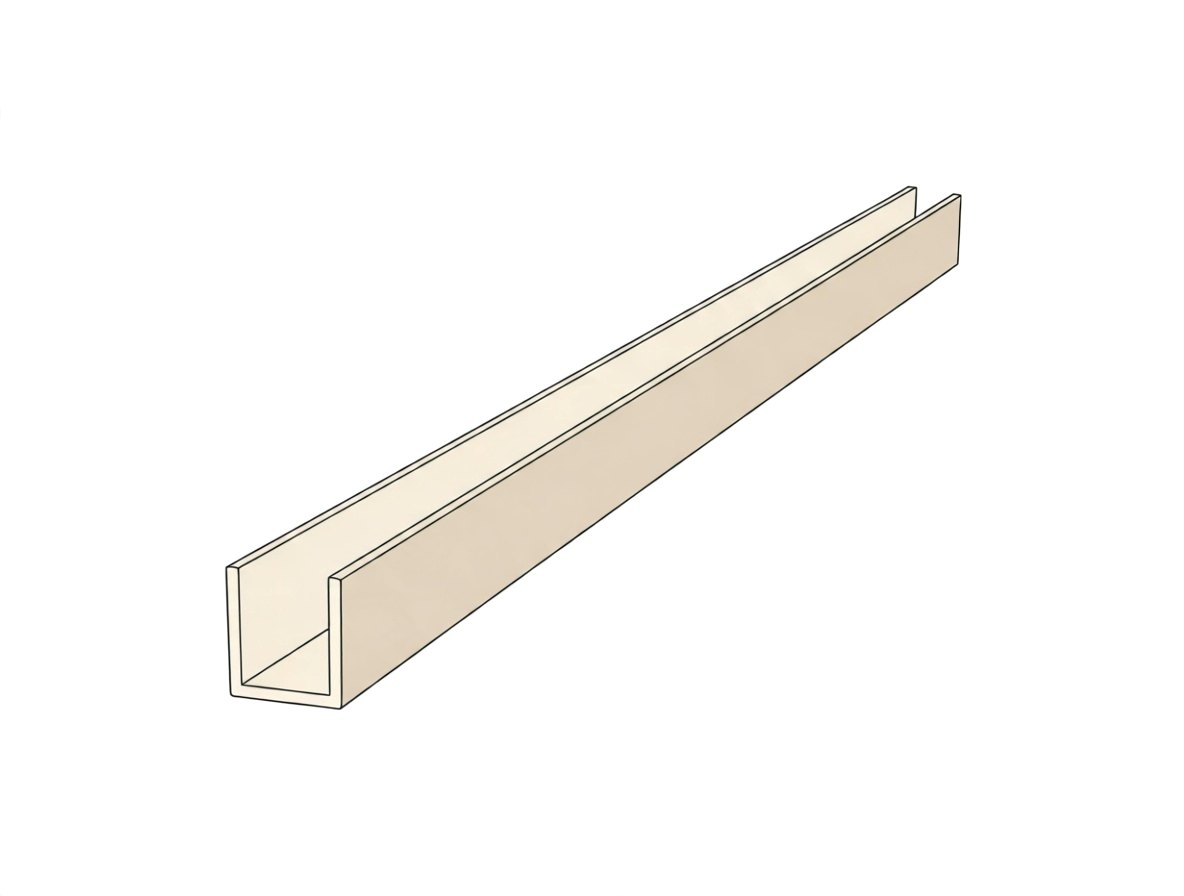
Female channel or routed groove on the door bottom, which receives a male floor- or wall-mounted guide pin, fin, or roller.
Usually connects to
- Sliding barn door guide pin
- T-style floor guide
- floor guide roller
- continuous floor guide fin
Common sizes
- Groove width typically 1/4 in to 3/8 in (6 mm to 10 mm) for fin/T-guides, up to 1/2 in to 3/4 in for small guide rollers; depth typically 1/2 in to 1 in (12 mm to 25 mm).
Where it is used
residential architectureinterior sliding doorsbarn door hardware installations
Variations
- Routed wood groove (mortised directly into door bottom)
- Extruded aluminum U-channel insert
- Floor-mounted U-channel guide
How to recognise it
Recognized as a continuous longitudinal U-shaped groove or aluminum channel recessed along the center underside of a sliding door slab.
Often confused with
| Confused with | How to tell them apart |
|---|---|
| Strut channel (Unistrut) | Strut channels are heavy-duty structural steel framing channels with inward-curling lips, whereas a barn door guide channel is a simple smooth U-profile groove or extrusion. |
| Sliding barn door top track | Top tracks carry the entire door load via wheeled trolleys/hangers; the bottom guide channel is non-load-bearing and only prevents lateral swinging. |
Also called
barn door bottom groovesliding door guide mortisecontinuous floor guide channelbottom door kerf
Good to know
In sliding barn door hardware terminology, bottom guiding is achieved either by routing a female groove/channel into the door bottom to ride over a floor guide, or by using external brackets (such as C-guides, roller guides, or adjustable U-guides) that cradle the door exterior without routing.
Design with real parts
Crafti checks which parts connect, right in your browser.